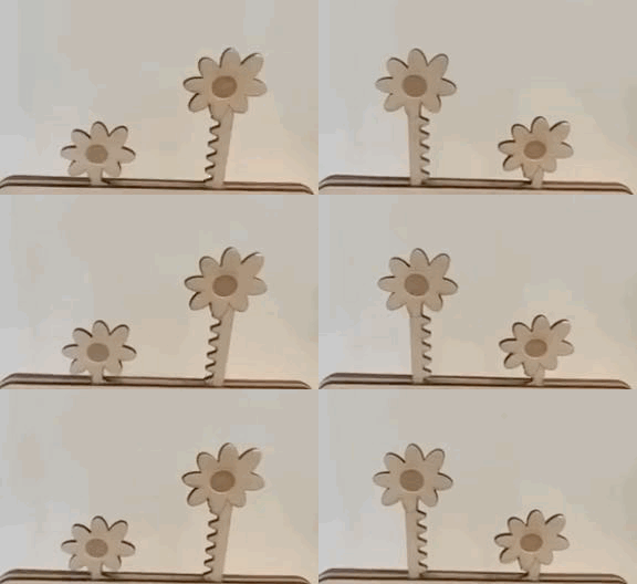
Linear to Rotary Motion: Blossoming Flowers

As I observe my surroundings, several everyday items create rotary motion with the use of gears. From the ticking clock hanging on my bedroom wall, to the wheels of a car or bicycle that take us to places, to a child’s toy with gears that constantly engages them— gears are visible everywhere and for a variety of uses. In UC Berkeley’s Prototyping and Fabrication course, we explored the application of gears through this project by converting rotary motion into linear motion.
Duration
October 2022
Roles
-
Determined how to implement gears to create linear motion.
-
Crafted design by hand and on Adobe Illustrator.
-
Laser cut and assembled all parts.
Skills
-
Diligent design planning
-
Clear vision
-
Skillful prototyping
-
Creative handrcrafting and laser cutting
Design Challenge
Design and laser-cut a set of gears, cams, or wheels to convert rotary motion into linear motion. The motion can be hand-powered or electro-mechanically powered, and the output motion should be highlighted by physical design.
Envisioning Design
Vision
I wanted to depict the beautiful phenomenon of flowers blossoming as the goal of this project. To accomplish this, my plan was to use a gear and gear racks to create the flowers’ linear motion. My vision was to place the gear in the center of the middle board, with the two gear racks on each side of the gear. The location of the gear racks is crucial, as it would need to be carefully placed close enough to the gear so that the gear teeth and gear rack teeth would touch each other when the gear was turned. As a result, this would cause the gear racks to move up and down, ultimately creating the blossoming flowers scene. The middle board would be sandwiched between the front board and the back board with dowels to make the entire mechanism stable and structured. Finally, the gear would be turned with a handle attached to the front board with a dowel, in the shape of a leaf, to match the entire floral theme.
Hand Sketches

Adobe Illustrator Sketches
Front, Middle, and Back Sides


Other Parts


Laser Cutting


Evolution of Design
Initial Design
The initial linear to motion mechanism design consisted of a front board and back board that sandwiched the middle board, which contained the gear and gear racks that produced the motion.

Updated Design
After receiving feedback and testing, I decided to add an acrylic window to the front board so that the audience would be able to view the source and process of the motion, creating a sense of wonder, amazement, and interest.

Testing
Initial Version
After ensuring that the initial design mechanism was working properly and as expected, I decided to add additional features, like the acrylic window, to enhance the design.

Updated Version
Then, after laser cutting the additional required parts, I tested the mechanism again to make sure it was working as anticipated.

Final Prototype

Acrylic Window, Portraying the Source of the Linear Motion

Output Motion

Final Product Prototype
Linear-to-Rotary Mechanism
-
The main purpose of this linear-to-rotary mechanism is for the flowers to move up and down when the handle is turned.
-
When a user turns the handle, one of the flowers moves up, and the other flower moves down.
-
The linear motion is generated by the work of a handle, gear, and two gear racks.
-
The gear, which is connected to the handle, moves when the handle is turned.
-
Once the gear moves, its teeth touch the teeth of the gear racks, causing them to move vertically.
-


Process Reflection
Surprises and Frustrations Encountered, and Lessons Learned
I learned that even minor mistakes can lead to significant issues. For instance, when attaching the stand to the board, it wasn't sticking properly. I discovered that one of the dowels was slightly protruding, probably by just a millimeter, preventing the stand from fitting correctly.
I learned the importance of precise measurements. Initially, I used a 0.25-inch hole for my dowel, but it was too loose. I tried various sizes, from 0.24 to 0.23 inches, before settling on 0.2375 inches after multiple trials and errors.
Additionally, I learned about the different techniques for clamping when ensuring the parts will stay properly attached. In this project, I made use of clamps and masking tape, so that the parts could stay as firmly together as possible as the glue dried.
Another important lesson I learned was the value of sanding! For example, at first, I had to place a lot of pressure when turning the handle for the gear to move. I then decided to sand the parts, and all of the pieces began to move a lot more smoothly.
